Category Archives: 3D

Seeing Old Battlefield Maps in a New Way

Previously, I’ve written about maps and layers in General Staff (here). A General Staff map is made up of background, elevation, terrain, slope, units, AI, water and road layers. Recently, while working with scans of very old battlefield maps, I discovered an amazing effect.

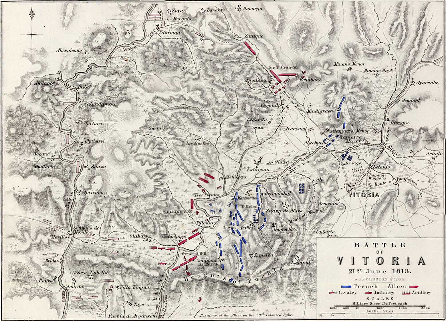
The battle of Vitoria. From, an “Atlas to Alison’s History of Europe: Constructed and Arranged, Under the Direction of Mr. Alison. 12 volume History of Europe (An Attractive And Complete Set Of Books Comprising Alison’s Europe).” The maps are made by W & A K Johnston Ltd, one of the major map publishing houses of the 19th century. William Johnston (1802–1888) and his brother Alexander Keith Johnston (1804–1871) originally trained as engravers, and founded the firm in 1826. The atlas, prepared by A K Johnston, was published by Wm Blackwood & Sons around 1850. Thank you, Mike Oliver for this background information on this map and the atlas that it came from. Click to enlarge.

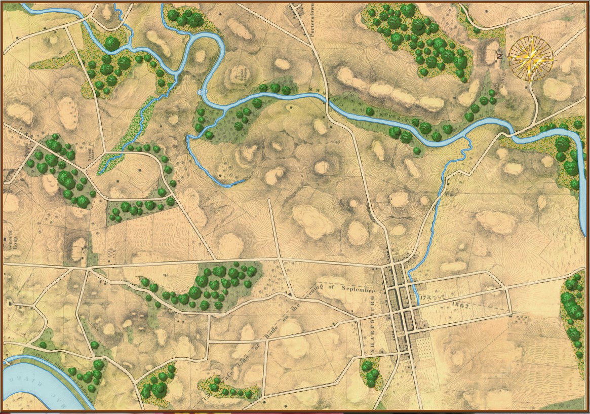
The above map comes from a wonderful atlas illustrating numerous Napoleonic era battles. These are the kinds of maps that inspired General Staff. As a kid I used to look at similar maps (and, of course, The West Point Atlas of American Wars) and imagine commanding units on the battlefield. The problem with maps like these is that they don’t actually contain any data that computers can use. Humans can look at the above map and see hills, valleys, towns and rivers. But, to a computer, this is just another image. The process of converting this map into computer usable data involves the General Staff Map Editor.

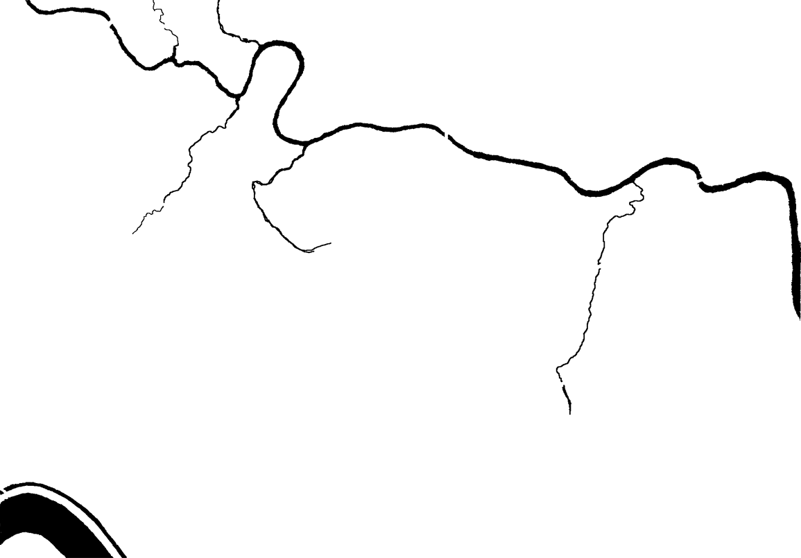
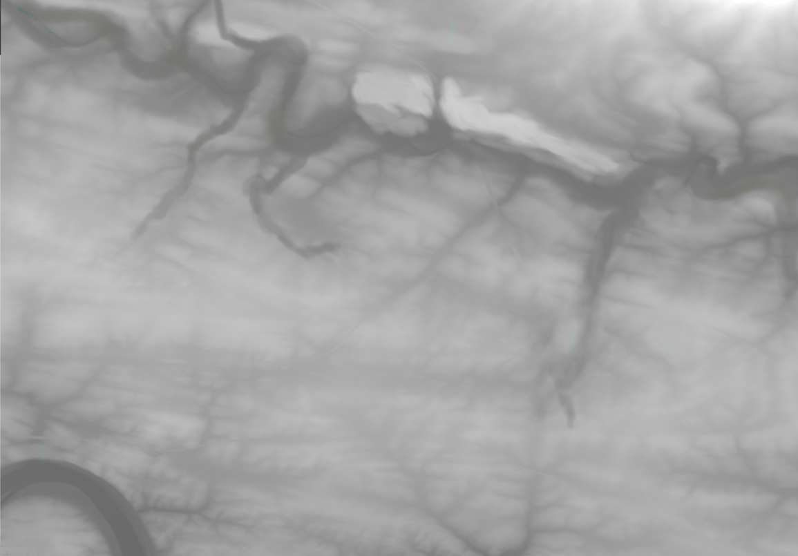
Ed Kuhrt, my old friend, superb musician, talented jeweler (he made my wife’s heart-shaped diamond ring), and excellent artist made this height map from the original map (above) using PhotoShop; though he could have used the General Staff Map Editor and a digitizing tablet as well.

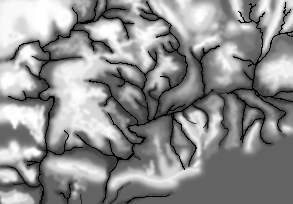
Height – or elevation – map produced by Ed Kuhrt from the Vitoria battlefield map. Click to enlarge.

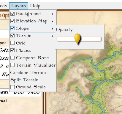
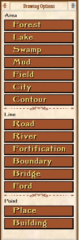
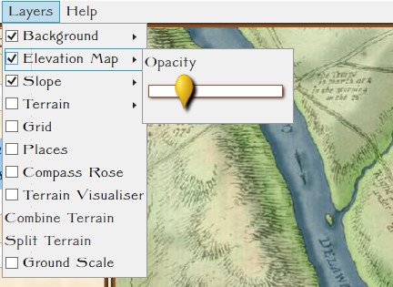
A slider and checkbox for adjusting the visibility (transparency) of the Slope Layer in the Map Editor.

Prior to this Andy O’Neill had just implemented precalculating slopes. In my original work with least weighted paths and slopes I calculated slope ‘on the fly’. Andy, quite correctly, realized that these values could be calculated in advance and stored as part of the map data. This, of course, would save time when calculating optimal paths for units (and also calculating combat equations which involve slope). Consequently, Andy added another visual layer – a slope layer – to visualize the slopes (see right).

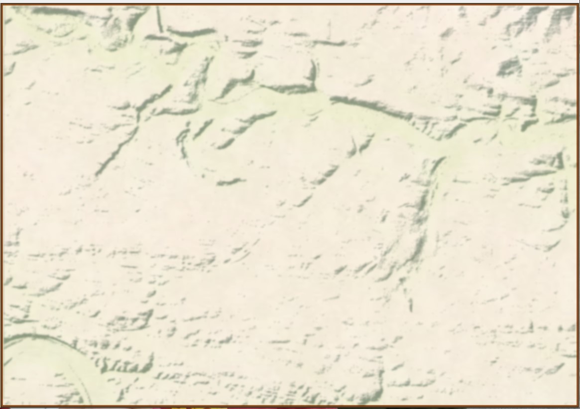
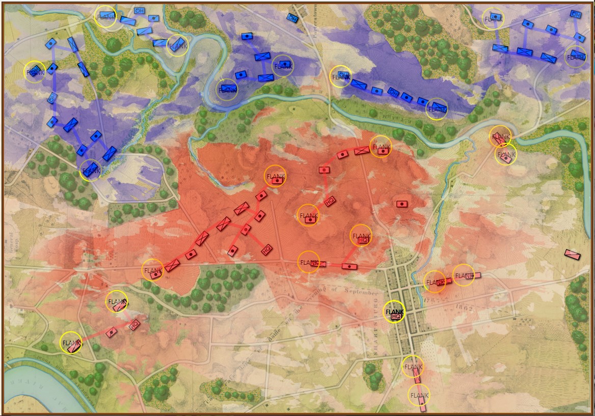
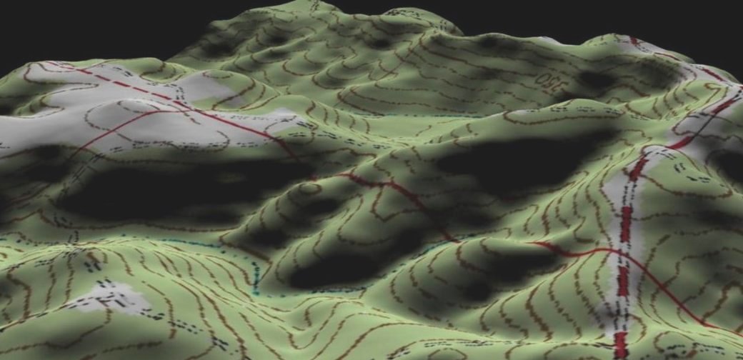
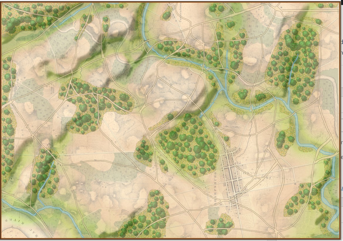
It was while working in the Map Editor with the Vitoria battle map, and adjusting the sliders for the various layers that I discovered this amazing effect:
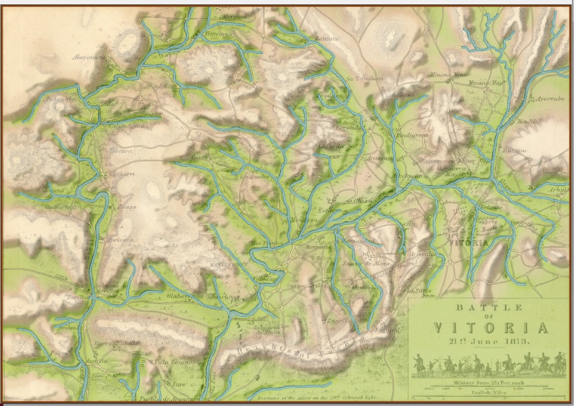
This map (above) certainly reminds me the plastic 3D maps we used to see back in grade school. I think they look fantastic. Here are some more:

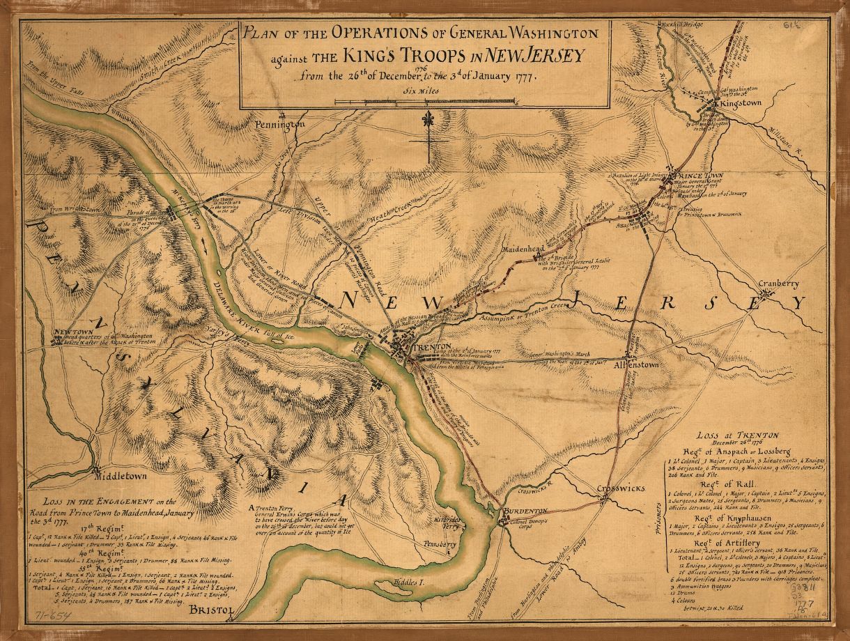
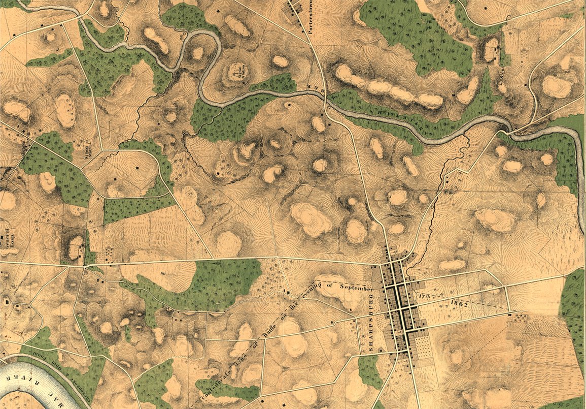
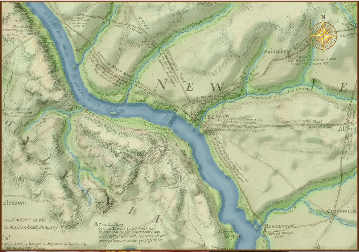
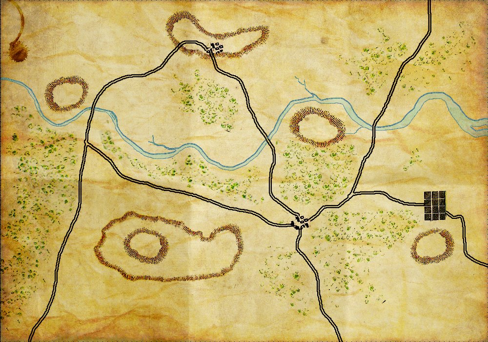
This map is from the US Library of Congress and can be downloaded here.

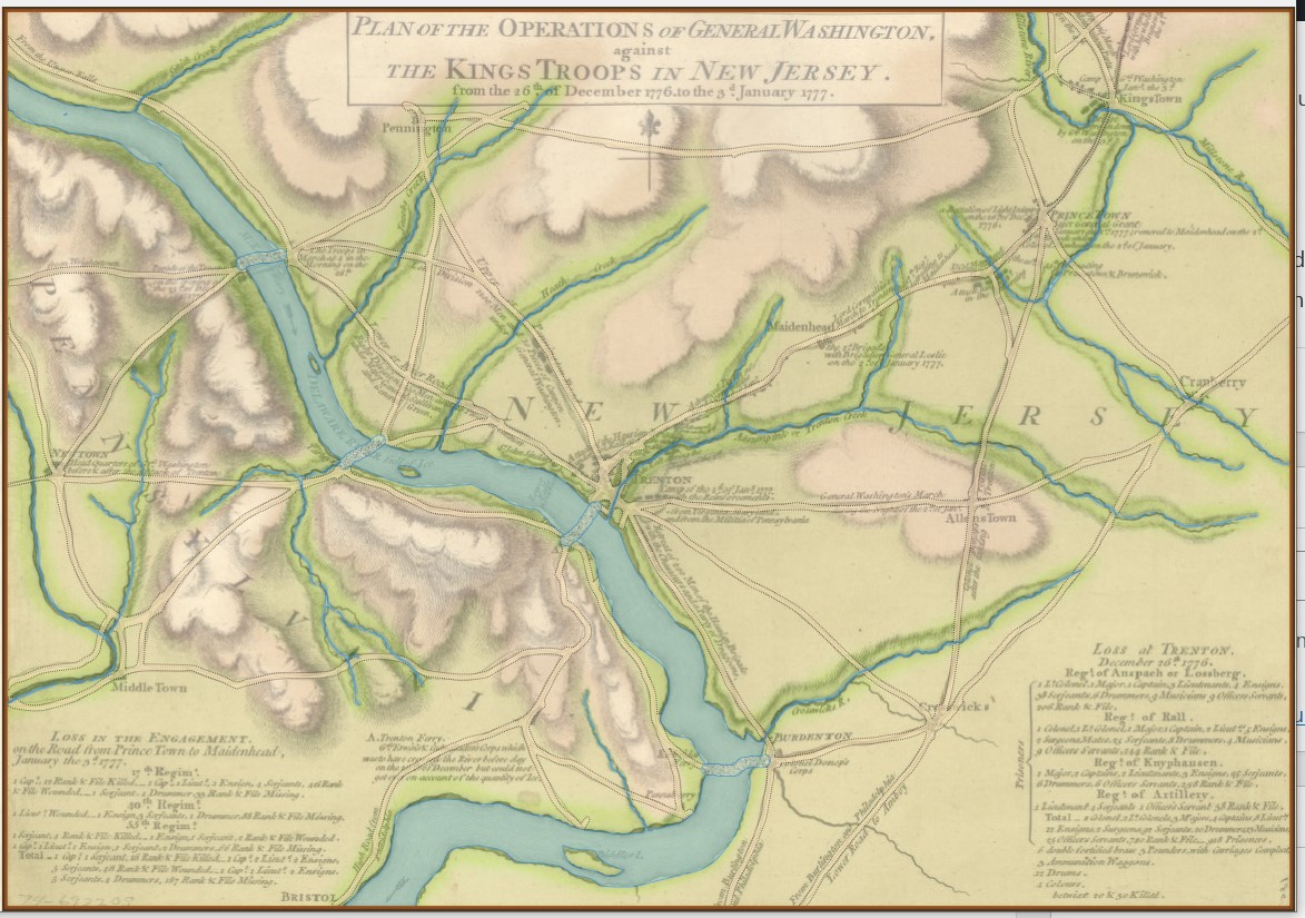
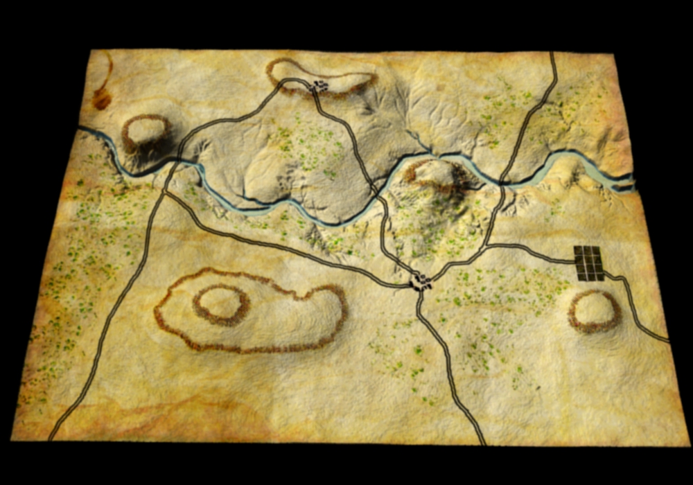
Trenton map with slope and elevation increased. Click to enlarge.

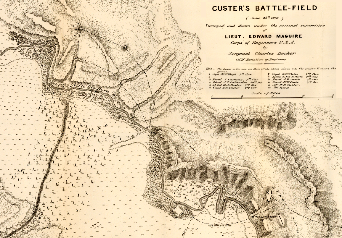
Fantastic map of the Little Bighorn battlefield done shortly after the battle. Click to enlarge.

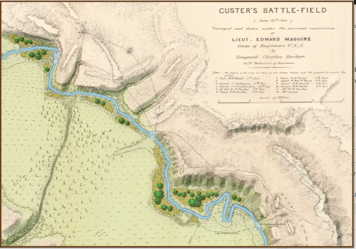
Little Bighorn battlefield with slope and elevation emphasized. Click to enlarge.

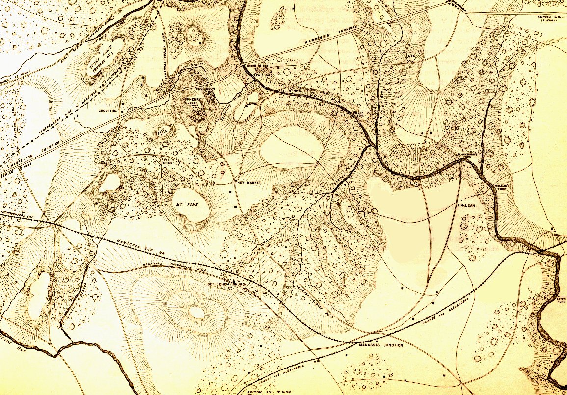
Battlefield of 1st Bull Run from the West Point Atlas of American Wars Volume 1. Click to enlarge.

1st Bull Run battlefield with slopes and elevation emphasized. Click to enlarge.

Layers: Why a Military Simulation Is Like a Parfait

Detailed military simulations and wargames are made up of layers1)Here is the obligatory link to Shrek and the layers, onions and parfait bit. by necessity. Layers keep simulation designers and users from being overwhelmed by oceans of data. In General Staff every scenario (battle) is made up of these layers (some are optional):

The Background Image. Ironically named because even though it’s underneath all the other layers it’s makes up most of what the user sees of the battlefield. However, the background image contains no data that is actually used by the computer; it is completely ‘eye candy’ for the user. That said, us humans get most of our data from looking at this map (we can make sense of the hills, roads, forests, rivers, etc.). But that’s not how computer vision works (see below).

The Background Image for the Antietam scenarios. Click to enlarge.

This map came from the Library of Congress (here). The Library of Congress is a great place to get royalty-free battlefield maps from American history. Personally, it’s exactly these old maps that inspired me to create General Staff. There is, however, one problem: these old maps are just not ‘GPS accurate’. That is to say, even though the General Staff Map Editor allows the user to directly import Google Maps elevation data, it won’t align properly with maps made over a hundred years ago without GPS data. That means the scenario designer will have to enter the elevation data by hand and not import it from satellite data.

The Terrain Layer. This layer is a visual display of what the computer ‘sees’ of the terrain: forests, water, fences, hedges, walls, swamp, mud, field, city, road, river, fortification, buildings (seven kinds), fords, and bridges.

The terrain layer for Antietam. Click to enlarge.

The Terrain Drawing tab (right). This is one of the tabs in the General Staff Map Editor (click here to go to the online Wiki for more detailed information). Click on the desired terrain type and then draw with either the mouse or a digitizing tablet and pen. I have absolutely no drawing abilities, but I’ve watched actual artists create a map using a digitizing tablet and pen in about 30 minutes. If you’re drawing a river, the harder you press with the digital pen the wider the river gets.

There are three ways you can input water and roads in the Map Editor: mouse, digitizing tablet and XAML code. For me, because I have very limited drawing abilities, I find using XAML code the easiest (below):

The Road Net Layer (optional). This image (below) was created in a paint program (PhotoShop, though any paint program that you’re comfortable with will work just fine). It was then imported into Inkscape (free download here) and exported as XAML.

The road net at Antietam. Click to enlarge.

The Water Layer (optional). Like the Road Net image (above) this was created in a paint program (PhotoShop). It was then imported into Inkscape (free download here) and exported as XAML.

Antietam water map. Click to enlarge.

The Elevation Layer. There are four ways to input elevation in the General Staff Map Editor: you can draw with the mouse, use a digitizing tablet and pen, input elevation data directly using Google Earth and directly importing a BMP image.

Antietam height map. Click to enlarge.

The Slope Layer. This layer shows the extrapolation of slopes from the elevation layer (above). Combined with the Background, and Elevation layer it can produce a dramatic 3D effect. See Trenton, below.

The Slope Layer for Antietam. Click to enlarge.

Blending Multiple Layers. This is a blend of the Background, Elevation, Terrain and Slope layers. The user can set the blend values (see screen shot from the Map Editor, right).


Antietam with background, elevation, slope and terrain blended. Click to enlarge.

The Places and Victory Points Layer. This layer allows you to set certain locations as Victory Points or Placenames. A Placename is a descriptive text placed on the map that has no importance to the simulation; e.g. labeling the Potomac River (below).

The Victory Point and Placenames Layer. Click to enlarge

The Units Layer. This is a visual representation of the current simulation state showing unit locations. This information may be filtered by Fog of War (FoW) and what units can observe other units (both friend and foe) using 3D LOS (see below):

The Units layer for Antietam. Note: reinforcements are displayed on this layer even though they won’t enter the scenario until later. This screen shot was taken from the Scenario Editor. Click to enlarge.

The Fog of War Layer. This layer is a visual representation of what can be observed from any point on the battlefield; in this case, the 3D LOS view from the Pry House (McClellan’s Headquarters at Antietam).

Antietam with complete Fog of War displayed for McClellan’s HQ at the Pry House. Click to enlarge.

The AI Layer. This layer is a visual representation of the output of a number of AI algorithms including Range of Influence (ROI), battle groups, and flank units. This is how the AI ‘sees’ the battlefield.

The AI Layer displays Red and Blue Range of Influence. Click to enlarge.

Trenton. I recently began working on a Trenton scenario. One of the best places to begin a search for a contemporary map of an American battle is the US Library of Congress. That is where I found the extraordinary campaign map for Trenton published in 1777.

From the US Library of Congress (published 1777, London). Click on the map to go to source.

From the above original map, Ed Kuhrt created an elevation or height map (see above) in PhotoShop. From that Elevation Layer we extrapolated the slopes and displayed them using an algorithm created by Andy O’Neill. When blended together the result is striking:

Screen shot of the Trenton map in the General Staff Map Editor. Note how the blending of the slope layer with the elevation and original background create a 3D effect. Click to enlarge.

References

References
1 Here is the obligatory link to Shrek and the layers, onions and parfait bit.

2D or Not 2D That is the Question (Redux)

We have been going back and forth on the question of: should General Staff have a 2D or 3D battlefield? Arguments can be made on both sides. The key points for 3D are:

  • we already are storing all the necessary data (we know the height of every square meter on the battlefield)
  • we have topographical maps that we can use for the 3D texture
  • being in 3D may increase General Staff‘s popularity
01TopographicalMap

A General Staff topographical map in 2D. (Click to enlarge.)

So, after going  back and forth on this issue for many months, we finally did some tests (thanks Ed Isenberg!). And here is what the same topographical map looks like utilizing our stored elevation data:

The same topographical map rendered in 3D. (Click to enlarge.)

The same topographical map rendered in 3D. (Click to enlarge.)

Well, it’s definitely 3D. But, it appears to me, that we’ve lost more than we have gained. The user hasn’t acquired any new information; hills, rivers, ridges and valleys were all quite apparent in the 2D map. We’ve also lost that wonderful historical Kriegsspiel feel of Victoriana typography and cartography. Our 3D display looks like a wrinkled pigskin and not a map that was used by the General Staffs of the great armies of the world. Also, not being in 3D will facilitate porting General Staff to smartphones.

We certainly would like to hear your opinion. But, as things stand now, General Staff will be moving forward in 2D.

2D or not 2D (that is the question).

Let’s just start off by saying that General Staff will be in 3D. It’s the only way to display the blocks that represent units. But the question is: should the map be flat with just 3D unit blocks (simulating the original Kriegsspiel ) or should we employ a technique that I used for a project for the  U. S. Army in which a 2D topographical map was used as the skin for 3D elevation that was extrapolated at runtime from USGS (United States Geological Survey) data?

A screenshot of a project that I did for the Army. Click to enlarge.

A screenshot of a project that I did for the U. S. Army. Click to enlarge.

There are certainly pros and cons for both ideas. Frankly, I like the idea of using a flat, 2D, map with only the unit blocks in 3D. However, the one thing I don’t like about ‘traditional’ Kriegsspiel is that the unit blocks are rigid and always perfect rectangles that do not conform to map contours or allow units to change formations.

On the other hand, I’m concerned that if we go full 3D (like in the above screen capture), it’s going to be to similar to current 3D wargames (I won’t mention names, here).

I’ve tried to keep the overarching theme of ‘simplicity’ for General Staff in clear view. General Staff is supposed to be a fun, simple game where the graphics don’t get in the way of a pure tactical, enjoyable real-time game.

Either way, we will be employing my optimized 3D Line of Sight (LOS) algorithms. That is to say, units behind ridges will not be visible to opponents.

What do you think? Send us a note or leave a reply.